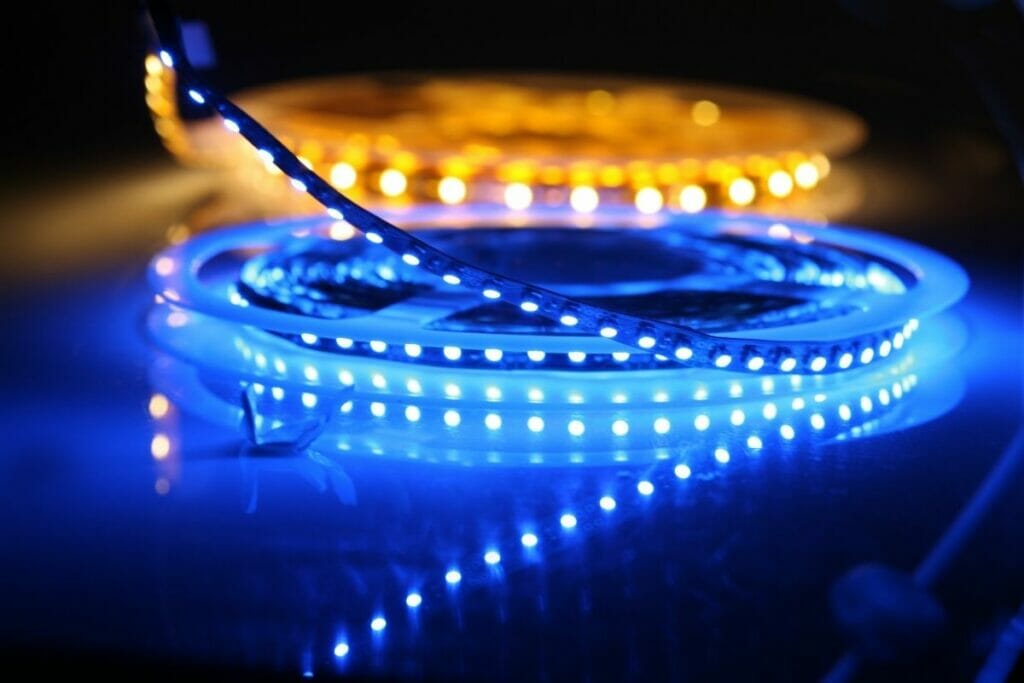
LED lighting has become very popular because of its energy efficiency and long life span. If you want to get started with programming LEDs, you’ll need some basic knowledge of electronics.
An LED light bulb uses less electricity than a regular incandescent or fluorescent light bulb. This makes them ideal for home and office applications where energy savings are important. They also last much longer than other bulbs.

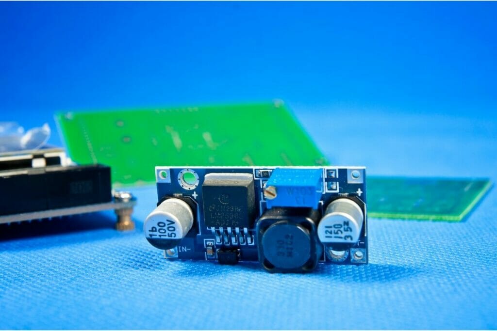
Programming LEDs involves using a microcontroller (MCU) to control the brightness of individual LEDs. The MCU communicates with the LEDs through a serial port.
There are several ways to connect the MCU to the LEDs, depending on the type of project you’re working on.
In this article we will explain how to use an Arduino board as your MCU and how to interface it with the LEDs. We will then go over the basics of creating a simple circuit that can be used in any application.
How To Program LED Lights
The first step is to decide which type of LEDs you would like to work with. You have two options:
1- RGBW – Red Green Blue White LEDs
2- RGB – Red Green Blue LEDs
We chose to work with RGBW LEDs because they offer more flexibility when it comes to color mixing. In addition, they offer better contrast ratios.
We will use WS2812B RGBW LEDs from Adafruit Industries. These are the most common types of RGBW LEDs. However, there are many different types available so make sure you choose the right one for your needs.
You can find all the components needed to complete this project at Adafruit Industries website. If you don’t already own an Arduino board, you can buy one from their website.
If you don’t already have an Arduino IDE installed on your computer, you can also easily download it from their site.
On the left side of the window, select Search for “Adafruit_NeoPixel”, click import, and install the library. Now let’s start building your project!
Step 1: Connecting The LEDs
- Connect the positive (+) pin of each LED to the 5V power supply rail.
- Connect the negative (-) pin of each LED directly to ground.
- Connect the GND pin of the MCU to ground.
- Connect VCC of the MCU to +5V rail.
Step 2: Setting Up The Code
Enter the following settings:
baud rate : 115200
data bits : 8
stop bits : 1
step size : 1
Now open the Arduino IDE.
Copy the contents of the file into notepad.
Save the file under the name NeoPixel.ino
Type the following lines of code:
/*
* NeoPixel Example by adafruit
*/
define NEOPIXEL_PIN 10 //the number of the neopixel connected to digital pin 13
define NUM_NEOPIXELS 16
void setup() {
Serial.begin(115200);
}
void loop() {
int pixel analogRead(A0);
Serial.print(“High”);
} else{
Serial.print(“Low”);
}
for (int i 0// initialize all pixels to their normal state (on)
NeoPixels .setBrightness(255);
NeoPixels .setColor(0x00FF0000);
NeoPixels.show();
}
Save the file.
Open the Arduino IDE again.
Click Open example.
Click Upload.
Your new code should now appear in the editor.
Step 3: Testing The Code
Make sure the baud rate matches the speed of your computer. If it doesn’t match, change the line Serial.begin(115200).
Now press upload.
After uploading the sketch, disconnect the power source and wait about 30 seconds before connecting the power source.
Once the power has been applied, plug the wires back into the pins. Check if everything works fine.
If the colors aren’t changing or the display isn’t showing anything, check the connections between the MCU and the LEDs.
Try making some changes to the code and see what happens.
For instance, try setting the brightness to 255 instead of 200.
Step 4: Creating A Custom Circuit

In this section, we will create a custom circuit using only the parts you need. This way you won’t have to purchase extra stuff later on.
1: Soldering The Circuit
The first step is soldering the circuit together. First, solder two wires to the positive (+) and negative (-) terminals of the battery pack.
Next, connect the red wire from the battery pack to the red terminal of the WS2812B. The black wire from the battery pack goes to the second red terminal.
Then, connect the blue wire from the battery pack with the third red terminal.
Finally, connect the white wire from the battery pack at the last red terminal. Now that the circuit is complete, cut off any excess wire.
2: Programming The Circuit
To make the circuit work, you must write a few lines of code.
First, enter the following settings:
baud rate : 115200
data bits : 8
stop bits : 1
step size : 1
Now open the Arduino IDE. Copy the following lines of code into notepad. Save them as NeoPixel.ino.
define NEOPIXEL1 11
define NEOPOLY2 12
SoftwareSerial mySerial(NEOPOLY2, 9600);
void setup(){
Serial.begin(9600);
mySerial.begin(9600, NEOPOLY2);
}
void loop(){
int val mySerial.read();
if (val ‘H’){
mySerial.println(‘L’);
}else{
mySerial.println(‘H’);
}
delay(1000);
}
You can find more information about how to use SoftwareSerial online both on their website and on other platforms.
3: Connecting The Circuit
Connect the circuit to your computer. Make sure the baud rate is set to 115200.
4: Running The Code
Run the code by pressing F5 in the Arduino IDE.
Step 5: Making Adjustments
Adjust the brightness of the NeoPixels. Change the color of the NeoPixels by changing the value of NEOPOLY2. For example, if you want to change the color to green, then change the number to 10.
Step 6: Saving The Code
Save the file as NeoPixel.ino in the same folder as the other files.
Step 7: Using The Circuit
When you are ready for the next steps, click upload.
Step 8: Adding An LCD screen
This part requires additional hardware. You’ll also need to add a breadboard and a transistor.
1: Adding A Breadboard
Add the components shown below to the breadboard.
2: Attaching The Transistor
Attach the transistor to the breadboard. The base should be connected to pin 13, while the emitter should be attached to pin 14.
3: Adding The LCD Screen
Add the components shown below to your breadboard.
4: Testing The Circuit
Test the circuit by connecting it to your computer.
5: Troubleshooting
If you’re having trouble getting the circuit to work, check out these troubleshooting tips.
6: Conclusion
That’s all there is to programming LEDs! You will now be able to program you LED lights exactly as you want to program them and create the lightshow of your dreams.
Why It Is Important To Know How To Program LED Lights
LED lights are incredible things. They allow us to brighten up our homes, decorate our Christmas trees and bring some color to our lives.
This is why it is so vitally important to know how to program them. If you don’t know how to program your LED lights then you are ultimately limited in what kind of wonderful lights you can have in your home.
So, if you haven’t ever attempted to program your LED lights before, now is the chance to do it. Don’t waste time, start programming today!
